
A hydraulic rotary actuator can provide a compact and controlled method for deploying access ramps on special-purpose vehicles, trailers, mobile service equipment, and industrial machinery.
An access ramp appears to perform a simple movement: rotate downward for loading or access, then return to the stored position. In practice, the mechanism must carry the ramp weight, resist gravity, stop smoothly, and remain secure during both operation and transport.
A helical hydraulic rotary actuator generates rotation directly at the pivot point. By combining rotary movement, mounting support, and bearing functions in one unit, it can simplify the ramp mechanism and reduce the number of external moving components.
How Does a Hydraulic Rotary Actuator Control Ramp Deployment?
During deployment, the ramp rotates from a vertical or folded transport position toward the ground. The actuator must control this movement rather than allowing the ramp to fall under its own weight.
Hydraulic pressure drives the actuator through a defined rotation angle. The ramp can therefore move gradually through the entire operating arc instead of depending on gravity for downward movement.
This provides better control when:
- The ramp is heavy or positioned above ground level
- The vehicle is parked on an uneven surface
- Personnel or equipment are close to the moving structure
- The ramp must stop before reaching the ground
- The mechanism needs to return to a compact transport position
- The movement must remain stable in both directions
Direct rotary output also keeps the actuator close to the main pivot. The torque acts on the ramp around the same axis used for deployment, reducing the need for a separate linkage to convert linear cylinder movement into rotation.
Why Can Cylinder-and-Linkage Ramp Systems Become Complicated?
A hydraulic cylinder produces linear movement. To rotate a ramp, that linear force must be transferred through a lever, crank, or linkage connected to the ramp pivot.
The effective turning force changes as the linkage angle changes. At one point in the movement, the cylinder may have a favorable lever arm. Near the folded or fully deployed position, the mechanical advantage may become much lower.
This can lead to several design challenges:
- The cylinder must provide enough force at the least favorable angle
- A longer stroke may be required to achieve the full ramp movement
- Larger mounting brackets may be needed
- The linkage must avoid interference throughout its arc
- Pins and joints require regular inspection
- Clearance may increase as the connections wear
A rotary actuator avoids much of this geometric variation by producing torque directly at the rotating output flange.
The hydraulic pressure still determines available torque, but the system does not depend on a long external lever to create rotation. This can make the movement more consistent throughout the deployment cycle.
Controlling the Ramp as Gravity Changes Direction
The load acting on an access ramp changes continuously as it rotates.
When the ramp is close to the vertical transport position, much of its weight acts near the pivot axis. As the ramp moves toward the horizontal position, the center of gravity moves farther away from the pivot, increasing the overturning moment.
The actuator may therefore experience a greater load near the lower part of the movement than at the beginning.
Ramp design should consider:
- Total ramp weight
- Distance from the ramp center of gravity to the pivot
- Added weight from handrails, surface panels, or extensions
- Dynamic force when the ramp starts or stops
- Vehicle inclination
- Wind acting on a large ramp surface
- Load direction at different angles
Torque selection cannot be based only on the ramp’s total weight. A relatively light but long ramp may create a significant moment because its center of gravity is positioned far from the rotation axis.
Why Holding Torque Matters After the Ramp Stops
Driving torque moves the ramp, while holding torque helps keep it in position after movement stops.
This distinction is important when the ramp is stored vertically or held at an intermediate angle. Gravity may continue applying torque even though hydraulic flow has stopped.
If the actuator and hydraulic circuit cannot hold the load, the ramp may gradually lower or shift away from its intended position.
Stable holding is useful during:
- Transport with the ramp folded
- Temporary positioning before full deployment
- Maintenance work around the ramp
- Loading preparation
- Operation on slightly inclined ground
Mechanical transport locks may still be required depending on equipment design and safety requirements. Hydraulic holding should not automatically replace a dedicated mechanical locking device where regulations or operating risks require one.
Counterbalance Control for an Overrunning Ramp Load
A ramp lowering under gravity can become an overrunning load. The load attempts to rotate the actuator faster than the hydraulic flow supplied by the control valve.
Without proper control, the ramp may accelerate unexpectedly, stop harshly, or create low pressure and unstable movement in one side of the hydraulic circuit.
A counterbalance valve can help regulate this condition by maintaining back pressure and controlling the release of oil from the loaded side of the actuator.
It can also help limit uncontrolled movement if a hydraulic hose loses pressure.
Counterbalance protection is especially relevant when:
- The ramp is heavy or long
- The ramp lowers mainly under gravity
- Personnel may stand near the movement area
- The equipment operates on slopes
- A hose failure could allow rapid rotation
- The ramp must remain stable at intermediate positions
The valve setting must be matched to the ramp load and hydraulic system. Excessive setting pressure can make the movement slow and increase heat, while insufficient pressure may not control the load effectively.
Choosing Between Cantilever and Straddle Support
The way the ramp is attached to the actuator affects the load carried by the output shaft and bearings.
In a cantilever arrangement, the ramp is supported mainly from one side of the actuator. This can create a compact structure, but it also places bending and overturning moment on the output.
In a straddle-mounted arrangement, the rotating structure is supported on both sides. The load is distributed more evenly, which is generally more suitable when the ramp is wide, heavy, or exposed to high external forces.
The actuator mounting surface must also remain rigid. A high-capacity actuator cannot compensate for a weak bracket or flexible frame.
Why 180-Degree Rotation Is Useful for Ramp Mechanisms
Many access ramps do not require continuous rotation. A controlled movement of up to 180 degrees can cover the complete cycle from folded storage to ground deployment.
The actual working angle may be lower than the actuator’s maximum rotation, but the available range gives flexibility when designing:
- Vertical folding ramps
- Underbody access panels
- Service platforms
- Trailer loading ramps
- Machine access steps
- Equipment covers or hatches
Mechanical stops and control settings should define the usable movement. Hydraulic hoses, handrails, sensors, and surrounding structures must also be checked throughout the full arc.
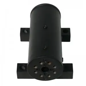
WEITAI WL20 Series Hydraulic Rotary Actuator
The WEITAI WL20 Series is a compact helical hydraulic rotary actuator designed for access ramps, platforms, booms, hatches, conveyors, and other rotating mechanisms. Its front-flange output and foot-mounted housing provide direct torque transmission while reducing the need for external shafts, bearings, and linkages. Cantilever or straddle mounting, optional counterbalance valves, BSPP or SAE ports, and customized interfaces are available for different equipment structures. Final configuration should be based on torque, moment load, mounting stiffness, hydraulic pressure, and operating conditions.
Conclusion
A hydraulic rotary actuator can simplify access ramp deployment by generating controlled rotation directly at the pivot point.
Compared with a cylinder-and-linkage system, it can reduce external joints, shorten the drive structure, and provide a more compact installation. Integrated load support and optional counterbalance protection are particularly useful when the ramp must lower under gravity and remain stable after movement stops.
The WEITAI WL20 Series combines 180-degree rotation, compact foot mounting, front-flange output, and defined drive, holding, and moment capacities. When correctly matched to ramp weight, center of gravity, hydraulic pressure, mounting method, and safety requirements, it can provide a practical rotary solution for special vehicles and mobile equipment.
Frequently Asked Questions
Can a hydraulic rotary actuator control a heavy access ramp?
Yes, provided that drive torque, holding torque, moment capacity, and mounting structure are matched to the ramp weight and center-of-gravity position.
Why is a counterbalance valve useful on a ramp?
It helps control a gravity-driven load, maintain stable lowering speed, and reduce the risk of uncontrolled movement if hydraulic pressure is lost.
Should an access ramp use cantilever or straddle mounting?
Cantilever mounting is more compact, but straddle mounting distributes the load across both sides and is generally more suitable for higher moment loads.
What rotation angle does the WL20 Series provide?
The listed WL20 configuration provides 180-degree rotation, which can cover folding, deployment, positioning, and return movements for many ramp and access mechanisms.
Post time: Aug-04-2026