
Compact mobile machinery often requires a rotary mechanism that can generate high torque, support external loads, and maintain a stable working angle without occupying excessive installation space. Traditional systems using hydraulic cylinders, linkages, pins, external bearings, and mounting brackets can complete the required movement, but they may also increase the number of components and create additional wear points.
A helical hydraulic rotary actuator combines rotary movement, load support, and structural connection within one enclosed unit. This makes it suitable for construction machinery, aerial work platforms, drilling equipment, material-handling systems, and special-purpose vehicles.
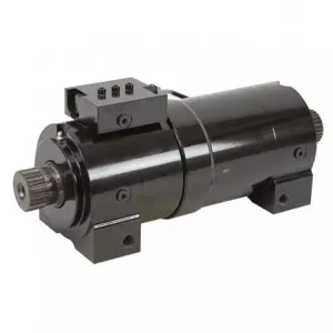
The WEITAI WL40 Series WL40-028 provides 220° rotation, 2800 Nm drive torque, and 6100 Nm holding torque at 21 MPa. Its compact foot-mounted structure allows it to be installed directly at the rotary joint of a boom, platform, attachment, mast, or mechanical arm.
How Helical Gearing Converts Hydraulic Power into Rotation
A conventional hydraulic cylinder produces linear motion through the extension and retraction of a piston rod. A helical hydraulic rotary actuator uses an internal gear system to convert similar axial piston movement into controlled rotary output.
When pressurized hydraulic oil enters the actuator, it pushes the internal piston along the housing. Helical teeth on the piston engage with matching internal gears and the output shaft. As the piston moves axially, the helical gear geometry forces the shaft to rotate.
Supplying oil through the opposite port reverses the piston movement and changes the rotation direction. This allows the actuator to perform repeatable clockwise and counterclockwise movement within its designed angular range.
Because the gears, piston, bearings, and output structure are enclosed inside the housing, fewer external linkages are needed. The enclosed design also helps protect internal transmission components from dust, rain, mud, and other contaminants commonly found around mobile machinery.
Why 220° Rotation Is Practical for Mobile Equipment
Many machines do not need continuous 360° rotation. Instead, they operate repeatedly between defined positions. A platform may rotate from a transport position to a working position, while a drilling head may move across several operating angles.
The WL40-028 offers a 220° rotation range, providing greater movement than common 90° or 180° mechanisms without requiring a continuous slewing system.
This rotation range is suitable for:
- Boom and jib positioning
- Aerial platform basket rotation
- Drilling head adjustment
- Conveyor direction control
- Pipe-handling arm movement
- Vehicle ramp deployment
- Hatch and cover operation
- Mast and davit rotation
- Brush positioning
- Shotcrete nozzle control
Installing the actuator directly at the rotary joint can place the rotation center closer to the load. This helps reduce the size of external connecting structures and creates a cleaner machine layout.
What 2800 Nm Drive Torque Means in Operation
The drive torque rating represents the actuator’s ability to rotate a load. At 21 MPa, the WL40-028 produces 2800 Nm of drive torque.
During real operation, the actuator must overcome more than the weight of the rotating component. It may also need to manage bearing friction, starting resistance, structural inertia, offset loads, and external working forces.
Hydraulic pressure has a direct influence on torque output. Within the rated operating range, higher pressure creates greater rotary force, while lower pressure reduces the available torque. Stable pressure is therefore important for consistent movement.
The WL40-028 has a displacement of 775 cc. Hydraulic flow mainly determines rotation speed. Increasing the flow can shorten the operating cycle, but excessive speed may create strong inertia and impact when the actuator stops or changes direction.
A balanced hydraulic circuit should therefore provide enough flow for efficient movement while still allowing smooth acceleration and deceleration.
Why Holding Torque Matters after Rotation Stops
Drive torque moves the load, while holding torque keeps it in position after movement stops.
The WL40-028 provides 6100 Nm of holding torque at 21 MPa, considerably higher than its drive torque. This is important in applications where the load must remain stable at an intermediate angle.
An aerial work platform, for example, must hold its basket in a selected direction. A drilling mechanism may remain fixed while external reaction forces act on the joint. A boom or mechanical arm may continue to experience gravity and offset loading after hydraulic movement has stopped.
Without sufficient holding capability, the load may drift, rotate slowly, or move away from the required position. Strong holding torque improves stability and helps the rotary joint resist external forces.
For gravity-loaded or suspended applications, a counterbalance valve can further improve control. It helps prevent the load from driving the actuator faster than the hydraulic system intends and supports stable position holding when oil flow stops.
Supporting Radial, Axial, and Moment Loads
A hydraulic rotary actuator is often part of the machine’s load-bearing structure. It must therefore withstand forces acting in several directions.
The WL40-028 has:
- 2040 kg radial load capacity
- 2040 kg axial load capacity
- 4200 Nm maximum straddle moment capacity
Radial loads act perpendicular to the output shaft and may result from the weight of a platform, attachment, or mechanical arm.
Axial loads act along the shaft direction and can be caused by thrust, compression, or the mounting structure.
Moment loads usually occur when the center of gravity is positioned away from the actuator centerline. A long boom or offset attachment creates a lever effect that increases bending stress on the rotary joint.
As moment loading increases, the available drive torque may decrease. Reducing the distance between the load center of gravity and the rotation center can improve stability and reduce additional stress on the actuator and equipment frame.
A Compact Alternative to Linkage-Based Rotation
A conventional limited-angle rotary system may require a hydraulic cylinder, brackets, pins, linkages, bearing housings, and a separate rotary support. These components take up space and create several possible wear points.
Clearance around pins, linkage deformation, and bearing wear may gradually affect positioning accuracy. Additional components also increase the amount of alignment and maintenance required.
The WL40-028 integrates its transmission and supporting structures within one unit. It has an approximate housing diameter of 140 mm, an overall height of 173 mm, and an overall length of 417 mm without the optional adapter. Its weight is approximately 33.6 kg.
This compact structure allows it to fit inside vehicle frames, beneath platforms, between machine sections, or at the end of an articulated arm. Reducing external linkage components can also leave more space for hoses, valves, sensors, and other hydraulic equipment.
How Hydraulic Control Affects Rotary Stability
Actuator performance depends on more than the mechanical structure. Hydraulic flow, pressure, and valve configuration all influence movement quality.
A sudden increase in flow may cause rapid acceleration. If the actuator reaches the end of its rotation without slowing down, the internal gears, mounting structure, and connected load may experience strong impact.
Flow-control valves can regulate rotation speed and improve movement consistency. Directional valves determine how smoothly the actuator starts, stops, and reverses.
Counterbalance valves are useful in gravity-affected applications because they prevent uncontrolled movement. Pressure-relief devices can also reduce hydraulic shock and protect the gears, bearings, seals, and equipment structure.
Maintaining Reliability in Frequent Rotary Cycles
Construction and industrial equipment may complete hundreds of rotary cycles during a working day. Frequent starting, stopping, and reversing continuously load the gears, bearings, and sealing system.
Hydraulic oil cleanliness is especially important. Metal particles, dust, and seal debris can increase wear on internal gear surfaces and sealing components. Effective filtration helps protect the actuator during long-term operation.
Temperature control also affects performance. Excessive heat can reduce oil viscosity, increase internal leakage, and accelerate seal aging. Very low temperatures may increase fluid resistance and slow actuator response.
Clean hydraulic oil, stable operating temperature, controlled rotation speed, and rigid mounting all contribute to reliable performance in high-cycle applications.
Integrated Rotary Motion for Demanding Machinery
The WL40 Series 2800 Nm helical hydraulic rotary actuator combines rotary drive, holding capability, load support, and structural mounting in a compact hydraulic component.
Its 220° rotation range, 2800 Nm drive torque, 6100 Nm holding torque, and multidirectional load capacity make it suitable for machines that require repeated limited-angle movement under demanding conditions.
By reducing external linkages and supporting both movement and structural loads, the WL40-028 can simplify equipment design while providing stable rotary control for booms, platforms, attachments, drilling systems, and material-handling mechanisms.
Frequently Asked Questions
Can the WL40-028 rotate continuously?
No. It provides 220° limited-angle rotation and is designed for repeated positioning rather than continuous 360° rotation.
What is the difference between drive torque and holding torque?
Drive torque rotates the load. Holding torque keeps the load in position after the movement stops.
Does hydraulic flow determine actuator torque?
Hydraulic flow mainly controls rotation speed, while hydraulic pressure mainly determines torque output.
Why do offset loads affect actuator performance?
An offset load creates additional moment force around the actuator. Higher moment loads increase structural stress and may reduce the available drive torque.
Post time: Jul-17-2026